Audio interconnection 17
Audio patch bays
- Video
- Script
Welcome to this tutorial on audio patch bays.
The concept of an audio patch bay is easy to understand. Almost all studio equipment interconnects via leads plugged into sockets which are usually located on their rear panels. If you need to change these connections you must remove and reconnect these leads.
So why is that a problem? ...
- You may have difficulty getting to the connections if equipment is sited against walls or located inside cabinets.
- You may find that the cables are not long enough to make your new connection.
- It may not be immediately apparent what is connected to what (patch bays can be labelled).
- Your creative flow may be disrupted if you need to stop what you're doing to reconnect your equipment.
The solution is to run all the leads from your equipment to a centrally located series of labelled sockets called a patch bay. Equipment can then easily be interconnected with short patch cords (or patch leads).
Caption - Do you need a patch bay?
If you don't regularly change the routing of your equipment, you may not need a patch bay for all your connections, but it is likely that you will benefit from some of your equipment's interconnections being easily accessible. For example you may want to use an outboard compressor to control dynamics when recording with a microphone, and then the same device again later to compress an instrument during mixing.
Caption - What type of signals can I connect?
The most common use of patch bays is to route line, and mic level signals.
As a general rule, you can route any signal through an audio patch bay. However, it is unwise to connect multiple types of signal to a patch bay which, if accidentally patched incorrectly, could damage equipment. For example, you would not want to connect the output of a power amplifier to the input of a delicate mic pre-amp. Therefore, it is sensible to assign some types of signals to their own dedicated patch bays and ensure they are physically remote from each other..
Although less common in the project and home studio, audio patch bays may also be used to interconnect power amplifiers and speakers. Also, there are specialist types of patch bays available to handle digital electrical, digital optical, and MIDI signals.
Caption - Balanced and unbalanced patch bays
Patch bays are available in both balanced and unbalanced configurations. If you are considering a patch bay, and only have unbalanced equipment, you should still consider a balanced patch bay to ensure your studio is future proof. This is because a time will come when you will acquire a balanced device.
Also ..
- A balanced patch bay can easily be used with unbalanced signals.
- An unbalanced patch bay cannot be used with balanced signals.
Caption - Front socket connector types
Audio patch bays may be categorized by the 3 different front panel connector types they use ..
- Type A jacks - These use the standard musical instrument (keyboards, guitars etc) and semi-pro recording equipment 1/4" A gauge jack plug connector. Although convenient (instruments can be connected without the need of a conversion lead) A gauge jacks were never designed for heavy patch bay use and should be avoided if you plan to regularly re-patch equipment.
- Type B jacks (GPO) - These connectors were used in the early days of telephone exchanges when connections were made manually by operators. They are very robust and hard wearing. The plug is physically similar to Type A but the tip is shaped differently and the construction is generally more robust. You should never insert a Type A jack into a Type B socket.
- Bantam - Essentially a mini version of the Type B (GPO) jack. Developed by mixing desk manufacturers to allow a greater density of sockets in a given space.
Caption - Rear connector types
Manufacturers offer a variety of rear panel connector types ..
- solder terminals are reliable and cost effective, but reconfiguring a patch bay may take longer
- 1/4" jack connectors are convenient but connections can become intermittent, need cleaning, and inflate the purchase cost
- D-sub 25pin connectors are convenient if connected devices employ this connector type
- EDACs are a type of multi-pin connector which allow complete pre-wired looms to be easily connected
Caption - Tie bar
The rear of the patch bay should feature a tie bar to secure looms to and prevent strain on the connections.
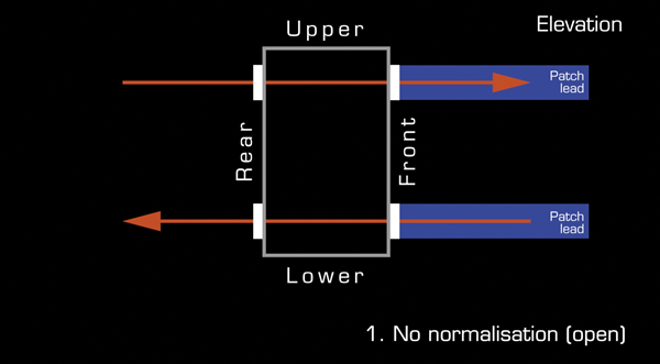
Caption - Normalisation
To minimise the need to use patch leads for every connection, normalisation is a wiring configuration whereby vertically adjacent sockets are permanently connected together even when no patch cord is plugged in. This allows you to have default connections which can be changed when required.
An example would be to have the outputs of a CD player connected to 2 sockets in an upper row, and the inputs to a mixers 2-track monitor return connected to 2 sockets in the row below, and have these connections normalised so that the devices are permanently connected. The connection would only be broken when patch leads are inserted into the top row sockets, perhaps in order to send the CD player outputs to a sampler.
There are 4 primary normalisation configurations
1. No normalisation - sockets are not connected
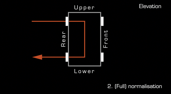
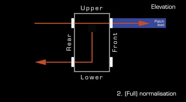
2. Normalisation - Vertically adjacent sockets are connected when no patch cord is present. When you insert a cord the connection is broken
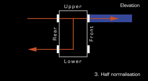
3. Half normalisation - Vertically adjacent sockets are connected when no patch cord is present. When you insert a cord the connection is maintained and an additional feed of the signal is taken
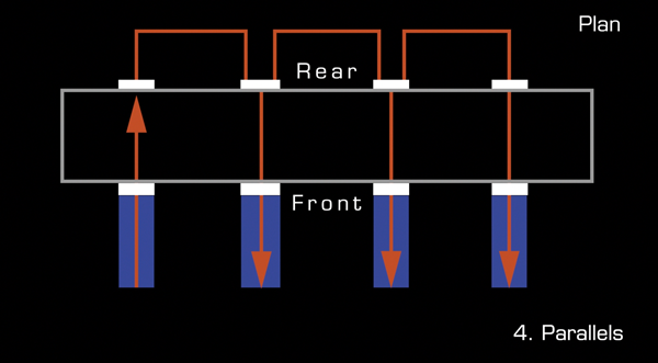
4. Parallels - multiple sockets are permanently connected so that copies of signals can be made
Most patch bay designs allow you to normalise vertically adjacent sockets by either changing the alignment a PCB or performing a simple solder.
Caption - How do you plan the layout of a patch bay?
There are no absolute rights or wrongs in setting up a patch bay, but the following are some of the standard practices employed by professional studio installation experts ..
- Create a list of all necessary connections and equipment.
- Group rows of sockets into categories, eg mixer inputs, stage box connections, audio interface connections.
- Create a diagrammatic illustration of the patch bay.
- Alternate between rows of outputs and inputs. Outputs above and inputs below.
- Ensure that connections to be normalised are vertically adjacent.
Caption - Thanks for watching
The script for this video, with accompanying images, can be found at projectstudiohandbook.com
We suggest you subscribe at our YouTube channel, and join our mailing list at our website to receive notification of new videos, blog posts and subscriber only extras.
Thanks for watching.